Lesson 6 of 16 · 20 min
Arduino Light Sensor: LDR Wiring and a Night Light
An LDR (light-dependent resistor) falls from about 1 MΩ in darkness to 10–20 kΩ in daylight; in a voltage divider with a fixed 10 kΩ resistor it turns light level into a 0–1023 reading on an analog pin.
This lesson also runs on an interactive 3D board: wire it, press Run and watch the circuit respond.
Open the 3D lessonA photoresistor — an LDR, light-dependent resistor — is a resistor whose value drops as light falls on it. GL5528, the part in most kits, is around 10–20 kΩ in daylight and about 1 MΩ in a dark room. On its own that is hard to measure, so you pair it with a fixed resistor to make a voltage divider.
With the LDR on the 5 V side and 10 kΩ to ground, bright light pulls the reading up towards 1023 and darkness drops it towards 0. Pick a threshold in between — around 300 for a normally lit room — and the sketch becomes an automatic night light.
What you need
| Part | Qty | Notes |
|---|---|---|
| Arduino Uno R3 | 1 | A0 reads the divider, pin 9 drives the LED |
| GL5528 LDR | 1 | Any photoresistor works; note its two values |
| 10 kΩ resistor | 1 | The fixed half of the divider |
| 220 Ω resistor + LED | 1 | The night light |
| Breadboard + 5 jumpers | 1 |
How to wire it
5 V → LDR → A0, and A0 → 10 kΩ → GND. Pin 9 → 220 Ω → LED → GND. Swap the LDR and the fixed resistor if you want the reading to rise in the dark instead.
| Pin | Connects to | What it does |
|---|---|---|
| 5V | LDR (left leg) | Top of the voltage divider. |
| A0 | LDR + 10 kΩ | The middle of the divider: higher when brighter. |
| GND | 10 kΩ | Bottom of the divider. |
| ~D9 | 220 Ω → LED | The night light. |
| GND | LED (−) | The LED’s return path. |
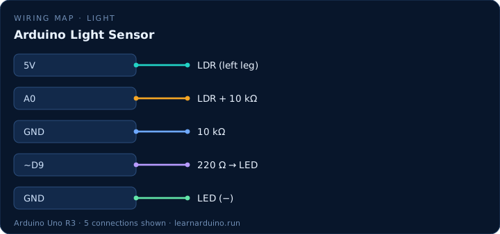
How an Arduino light sensor divider works
An LDR on its own gives you a resistance, and an Arduino measures voltage. The divider converts one into the other: 5 V → LDR → the analog pin, and that same pin → 10 kΩ → ground. The reading is 1023 × R_fixed ÷ (R_ldr + R_fixed), so it rises as the LDR's resistance falls — that is, as the room gets brighter.
The fixed resistor decides where the sensor is most sensitive. A GL5528 is around 10–20 kΩ at 10 lux and about 1 MΩ in the dark, so 10 kΩ puts the interesting range in the middle of the scale. A 1 kΩ resistor would leave the divider blind in dim rooms; 100 kΩ would saturate in daylight.
Turning readings into a usable threshold
Do not copy a threshold from a tutorial. A bright desk can read 800 while a dim corner reads 250, with identical code. Print the numbers in your own room, at the light level you actually care about, then put the threshold between the two states with room to spare.
A single threshold makes a night light oscillate at dusk: the LED lights the sensor, the sensor sees light, the LED goes out. Hysteresis fixes it — switch on below 280, switch off only above 340. Averaging five readings on top removes the last of the flicker.
The sketch
const int SENSOR = A0;   // middle of the LDR divider
const int LED = 9;       // the night light
const int DARK = 300;    // below this it counts as dark

void setup() {
  Serial.begin(9600);
  pinMode(LED, OUTPUT);
}

void loop() {
  int light = analogRead(SENSOR);  // 0 = dark, 1023 = bright
  Serial.println(light);

  if (light < DARK) {
    digitalWrite(LED, HIGH);       // dark: switch the light on
  } else {
    digitalWrite(LED, LOW);
  }
  delay(100);
}
What the code does
- analogRead(SENSOR) reads the middle of the divider: more light, less LDR resistance, higher voltage.
- The threshold is a judgement call — print the numbers in your own room first, then set it between the light and dark values.
- digitalWrite(LED, HIGH) inside the if, LOW in the else, keeps the two states explicit.
- delay(100) is fast enough to feel instant and slow enough to keep the serial monitor readable.
Specifications
| Item | Value |
|---|---|
| LDR | GL5528 photoresistor |
| In daylight | ≈ 10–20 kΩ |
| In the dark | ≈ 1 MΩ |
| Divider resistor | 10 kΩ to GND |
| Response time | ≈ 20–30 ms |
Common mistakes
- Putting the LDR straight between 5 V and the analog pin with no resistor. The pin then always reads 1023, whatever the light does.
- Copying someone else’s threshold. A bright desk and a dim corner differ by hundreds of counts; measure your own room.
- Expecting a linear response. LDR resistance is logarithmic in lux, so the reading changes fast at dusk and slowly at noon.
Sources
The figures in this lesson come from these documents. Every value in the tables above can be checked against them.
- GL5528 LDR — resistance against illuminance
- analogRead() — Arduino language reference
- Analog inputs — how the Uno's ADC works
Frequently asked questions
What is the difference between an LDR and a phototransistor?
An LDR is slow (20–30 ms) and fairly linear in resistance but drifts with temperature. A phototransistor is much faster and more sensitive, but you need to know whether it expects light or infrared.
Why does my LDR reading stay at 1023?
The divider is incomplete. You need one leg of the LDR to 5 V, the other to the analog pin, and a resistor from that same pin to ground. Without the resistor there is no current path.
Can I detect a flame or a flame-like flicker with an LDR?
Roughly. A flame gives a strong, fast flicker that an LDR can see, but an IR flame sensor is far more reliable. Use the LDR for ambient light levels, not for safety.
How do I make the night light stop flickering at dusk?
Add hysteresis: switch on below 280, switch off only above 340. The gap stops the light from triggering itself on and off at the threshold.
Want to see this circuit before you own the parts? The Arduino simulator draws this exact pin table on a 3D Uno R3: click any jumper to see what it carries, press Run and read the serial monitor.
Open the Arduino simulatorPublished 12 November 2026 · last updated 17 November 2026 · written and tested by Nick Hu.