Lesson 3 of 16 · 20 min
Arduino Push Button: Pull-Down, Pull-Up and Debounce
A push button on an Arduino is wired as a switch between a pin and either 5 V or ground, with a 10 kΩ resistor holding the pin at a known level when the button is open; the sketch reads it with digitalRead().
This lesson also runs on an interactive 3D board: wire it, press Run and watch the circuit respond.
Open the 3D lessonAn input pin with nothing attached is an antenna. It picks up mains hum and static, and digitalRead() returns a random mix of HIGH and LOW. A resistor to 5 V or ground — a pull-up or a pull-down — holds the pin at a defined level until you press the button.
The tidy way is the Uno’s built-in pull-up: pinMode(BUTTON, INPUT_PULLUP) connects about 20–50 kΩ inside the chip, so the pin reads HIGH at rest and LOW when the button shorts it to ground. That is one wire fewer and one resistor fewer than the classic pull-down circuit shown here.
What you need
| Part | Qty | Notes |
|---|---|---|
| Arduino Uno R3 | 1 | Any digital pin works; pin 2 is used here |
| Tactile push button | 1 | 4-leg 12 mm switch; legs are paired in pairs |
| 10 kΩ resistor | 1 | Brown-black-orange pull-down |
| 220 Ω resistor + LED | 1 | Shows the button state |
| Breadboard + 5 jumpers | 1 | A button needs a shared ground rail |
How to wire it
5 V → button left leg. Button right leg → pin 2, and the same point → 10 kΩ → GND. That is the pull-down. Pin 13 → 220 Ω → LED → GND for the indicator.
| Pin | Connects to | What it does |
|---|---|---|
| 5V | Button (left) | One side of the switch. |
| D2 | Button (right) + 10 kΩ | Reads HIGH while the button is held. |
| GND | 10 kΩ pull-down | Pulls D2 LOW when the button is up. |
| D13 | 220 Ω → LED | The output you control. |
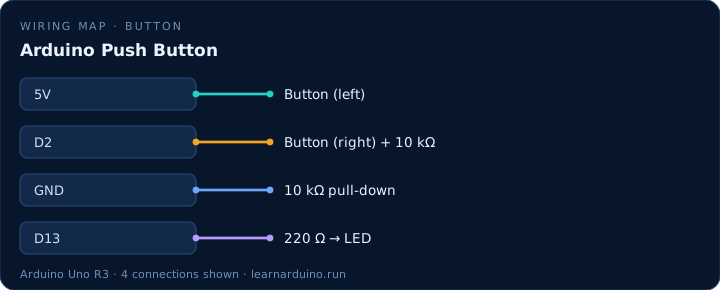
Wiring an Arduino push button without a floating pin
A pin in INPUT mode with nothing connected has an impedance near infinity, so it collects whatever noise is nearby and digitalRead() returns a lottery. The fix is a defined path to a rail: either a 10 kΩ resistor to ground with the button to 5 V, or the chip's own pull-up with the button to ground.
The internal pull-up is the better default. pinMode(BUTTON, INPUT_PULLUP) connects 20–50 kΩ inside the ATmega328P, the pin idles HIGH, and pressing the button shorts it to LOW. One wire, no resistor, and no way to short the supply by accident — which the 5 V-plus-resistor version can do if a leg lands in the wrong breadboard row.
Debounce a button without delay()
Contacts bounce. For 5–10 ms after a press the metal chatters, and a sketch that reads the pin every few microseconds sees a burst of presses. The naive fix, delay(50), freezes every other input for those 50 ms and is the reason beginner projects feel unresponsive.
The millis() pattern fixes both problems: record when the pin last changed, ignore further changes for 30–50 ms, and never stop the loop. If the button sits on D2 or D3 you can attach an interrupt instead, but keep the service routine short, mark shared variables volatile, and never call Serial or delay() inside it.
The sketch
const int BUTTON = 2;  // button + 10k pull-down
const int LED = 13;    // indicator LED

bool lit = false;      // toggle state
bool lastPressed = false;

void setup() {
  pinMode(BUTTON, INPUT);
  pinMode(LED, OUTPUT);
  Serial.begin(9600);
}

void loop() {
  bool pressed = digitalRead(BUTTON) == HIGH;

  // only react to the moment the button goes down
  if (pressed && !lastPressed) {
    lit = !lit;                 // one press, one change
    digitalWrite(LED, lit);
    Serial.println(lit ? "on" : "off");
    delay(30);                  // cheap debounce for a demo
  }
  lastPressed = pressed;
}
What the code does
- pinMode(BUTTON, INPUT) makes pin 2 a listener. Use INPUT_PULLUP and you can delete the 10 kΩ resistor.
- digitalRead(BUTTON) returns HIGH while the button is held down in this pull-down circuit.
- Hold mode copies the button straight to the LED with digitalWrite(LED, pressed).
- Toggle mode keeps a state variable and flips it only on the edge from released to pressed, so one press is one change.
Specifications
| Item | Value |
|---|---|
| Button | 12 mm tactile switch |
| Pull-down | 10 kΩ to GND |
| Logic levels | LOW < 1.5 V, HIGH > 3 V |
| Bounce | Contacts chatter for ~5 ms |
| Tip | INPUT_PULLUP needs no resistor |
Common mistakes
- Leaving the pin floating. The LED flickers on its own and the bug looks like broken code rather than a missing resistor.
- Wiring the button across 5 V and GND with no resistor. Pressing it shorts the supply; the board resets or the regulator overheats.
- Adding delay() for debounce inside loop(). A 50 ms delay makes every other pin feel laggy — debounce with millis() instead.
Sources
The figures in this lesson come from these documents. Every value in the tables above can be checked against them.
- digitalRead() — Arduino language reference
- pinMode() — Arduino language reference
- Arduino Uno Rev3 — official board specifications
Frequently asked questions
Do I need a resistor for a push button on Arduino?
Only if you use INPUT. With pinMode(pin, INPUT_PULLUP) the chip supplies an internal 20–50 kΩ pull-up and the button simply connects the pin to ground, so no external resistor is needed.
Why does my button trigger twice per press?
Contact bounce: the metal contacts chatter for about 5 ms. Either ignore readings taken within 20–50 ms of the last change, or debounce with millis() instead of delay().
Can one pin read several buttons?
Yes, with a resistor ladder: each button connects a different resistor to the same analog pin, and analogRead() tells you which one is pressed. Five buttons fit on one pin.
What is the difference between a pull-up and a pull-down?
A pull-up holds the pin at 5 V and the button pulls it to ground, so pressed reads LOW. A pull-down holds it at 0 V and the button pulls it up, so pressed reads HIGH. Both work; the internal pull-up is the one you get for free.
Want to see this circuit before you own the parts? The Arduino simulator draws this exact pin table on a 3D Uno R3: click any jumper to see what it carries, press Run and read the serial monitor.
Open the Arduino simulatorPublished 12 November 2026 · last updated 17 November 2026 · written and tested by Nick Hu.