Lesson 11 of 16 · 25 min
Arduino Temperature Sensor: TMP36 to Degrees
The TMP36 outputs 750 mV at 25 °C and changes by 10 mV per °C, so on a 5 V Arduino the temperature in °C is (analogRead(A0) × 5.0 / 1023 − 0.5) × 100.
This lesson also runs on an interactive 3D board: wire it, press Run and watch the circuit respond.
Open the 3D lessonThe TMP36 is the easiest analog temperature sensor to live with: three legs, no calibration, and a straight line from −40 °C to 125 °C. Its output is 0.5 V at 0 °C plus 10 mV for every degree above that.
Because the Uno turns 0–5 V into 0–1023, each ADC step is about 4.9 mV — roughly half a degree. That is plenty for a thermostat, a greenhouse monitor or a fan controller, and the same code works on a breadboard or inside a project box.
What you need
| Part | Qty | Notes |
|---|---|---|
| Arduino Uno R3 | 1 | A0 measures, pin 6 drives the fan |
| TMP36 sensor | 1 | Flat side facing you: 5 V, A0, GND |
| TIP120 + 1 kΩ | 1 | Only if you switch a real fan |
| 5 V fan | 1 | A 40 mm fan draws about 100 mA |
| Breadboard + jumpers | 1 |
How to wire it
TMP36 left leg (Vs) → 5 V, middle leg (Vout) → A0, right leg → GND. Keep the sensor away from the regulator and the USB chip: they warm the board by several degrees, so measure air, not the PCB.
| Pin | Connects to | What it does |
|---|---|---|
| 5V | TMP36 Vs (left) | Power for the sensor. |
| A0 | TMP36 Vout (middle) | 0.5 V plus 10 mV per °C. |
| GND | TMP36 GND (right) | Ground. |
| ~D6 | 1 kΩ → Base | Switches the fan through the transistor. |
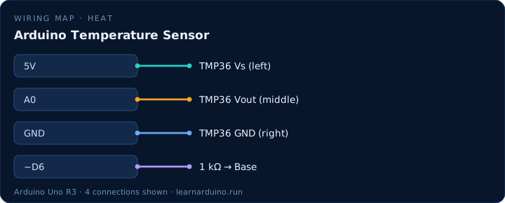
Reading an Arduino temperature sensor accurately
The TMP36 is a straight line: 0.5 V at 0 °C plus 10 mV for each degree, from −40 °C to 125 °C. The ADC turns that into a number, and one step of a 10-bit converter is about 4.9 mV, so the raw resolution is roughly half a degree before you average anything.
Accuracy is a different question from resolution. The part is specified at ±2 °C over its range and ±0.5 °C at 25 °C, so no amount of averaging turns it into a lab thermometer. Placement matters more than maths: sit it beside the board's regulator and you will be measuring the regulator, several degrees above the room.
From TMP36 readings to a thermostat
A thermostat is a threshold with hysteresis. Fan on above 28 °C, off below 26 °C — the gap stops it hunting on and off around a single number, the same problem the night light had in lesson 6.
Once the fan is on a PWM pin, the same reading can set its speed instead of just switching it: map 26–34 °C onto 80–255 and the noise rises with the heat. If you need better than ±2 °C, a DS18B20 gives digital readings over one wire and an SHT31 adds humidity on the same I2C bus as the OLED in lesson 14.
The sketch
const int SENSOR = A0;  // TMP36 Vout
const int FAN = 6;      // PWM through a transistor
const float LIMIT = 28.0;

void setup() {
  Serial.begin(9600);
  pinMode(FAN, OUTPUT);
}

void loop() {
  int raw = analogRead(SENSOR);
  float volts = raw * 5.0 / 1023.0;        // 0-5 V
  float tempC = (volts - 0.5) * 100.0;     // 10 mV per degree

  Serial.print(tempC, 1);
  Serial.println(" C");

  // above the limit: fan full on, below: off
  analogWrite(FAN, tempC > LIMIT ? 255 : 0);
  delay(200);
}
What the code does
- raw × 5.0 / 1023.0 turns the 0–1023 reading back into volts; the .0 matters, otherwise the maths stays integer.
- (volts − 0.5) × 100 converts the offset and the 10 mV per degree slope into °C in one step.
- The fan switches on through the transistor exactly as in the motor lesson — a pin cannot power a fan.
- delay(200) is a comfortable sample rate; the sensor settles long before that.
Specifications
| Item | Value |
|---|---|
| Sensor | TMP36, −40 to 125 °C |
| Output | 10 mV/°C, 750 mV at 25 °C |
| Accuracy | ±2 °C |
| Fan | 5 V DC, switched by a TIP120 |
| Reading | every 200 ms |
Common mistakes
- Reading the sensor while it sits next to the voltage regulator. The board warms the air around it and you measure the Arduino, not the room.
- Doing the maths in integers. raw * 5 / 1023 gives 0, 1, 2 … and you lose every fraction of a degree.
- Wiring the TMP36 backwards. With the flat side facing you the order is power, signal, ground — reversed it reads nonsense and gets warm.
Sources
The figures in this lesson come from these documents. Every value in the tables above can be checked against them.
- TMP36 — 10 mV/°C analog temperature sensor
- analogRead() — Arduino language reference
- Analog inputs — how the Uno's ADC works
Frequently asked questions
How accurate is the TMP36?
±2 °C over its range and ±0.5 °C at 25 °C, which is fine for a thermostat or a data logger but not for anything that needs lab accuracy. For that, use a DS18B20 or an SHT31.
What is the difference between TMP36 and LM35?
They look identical and are wired differently: the LM35 outputs 0 V at 0 °C and 10 mV/°C, so no offset; the TMP36 starts at 0.5 V so it can also read below zero. Check the part number before copying code.
Why does my temperature reading jump around?
ADC noise of one or two counts is normal. Average ten readings, add a 100 nF capacitor from Vout to ground, and keep the sensor leads short.
Can I read temperature without a sensor?
The ATmega328P has an internal bandgap temperature sensor, but it is uncalibrated and only good to a few degrees — useful for detecting overheating, not for measuring a room.
Want to see this circuit before you own the parts? The Arduino simulator draws this exact pin table on a 3D Uno R3: click any jumper to see what it carries, press Run and read the serial monitor.
Open the Arduino simulatorPublished 12 November 2026 · last updated 17 November 2026 · written and tested by Nick Hu.